
Choosing the best Single Gauge Manifold begins with the system, not the product label. In field service, technicians often compare brass bodies, valve layouts, hose ratings, and gauge readability. A manifold that feels solid on a bench may become awkward inside a cramped service panel. Pressure range matters. So does accuracy. For refrigeration, HVAC, laboratory, and industrial work, the correct choice depends on compatible refrigerants, expected pressures, connection standards, and measurement conditions. A clear scale can prevent a rushed reading. A durable sight glass can reveal movement, contamination, or an unexpected pressure change. These details connect specifications with real use.
This guide evaluates Single Gauge Manifold designs through practical selection criteria and manufacturer documentation. It considers gauge accuracy, calibration information, material compatibility, hose quality, valve control, temperature limits, and service support. Independent standards and verified technical data deserve more trust than glossy claims. Still, no single model suits every technician or application. That is the uncomfortable part. A low-cost unit may work well for occasional maintenance, while frequent field use may justify stronger valves and replaceable hoses. We should also admit that published accuracy can change with impact, heat, age, and poor handling. Careful users check the zero position before connection and compare readings against known conditions when possible. The goal is not to declare a universal winner. It is to identify the safest, clearest, and most dependable fit for the work ahead.
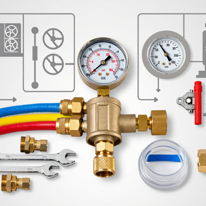
The best single gauge manifold depends on pressure, temperature, fluid compatibility, and maintenance needs. A two-valve design usually combines an isolation valve with a bleed valve. The isolation valve separates the gauge from the process line. The bleed valve releases trapped pressure from the gauge side.
This arrangement makes inspection and replacement more controlled. Close the isolation valve before loosening any gauge connection. Then open the bleed valve only after confirming the gauge side is safe to vent. Never assume a closed valve has stopped all pressure. Verify it.
Small details matter. A technician should check the body material, seal material, pressure rating, port size, and temperature range. Stainless steel may suit demanding environments, but compatibility still requires review.
The gauge connection should remain aligned and properly supported. Strain can damage threads or create leaks.
A clear valve label helps. So does a visible vent path. Bleed outlets should point away from people and sensitive equipment. In real installations, access is sometimes treated as an afterthought. That is a mistake. A compact manifold can save space, yet poor access can slow maintenance and increase handling errors. Regular leak checks and calibration records support reliable readings over time.
What Is the Best Single Gauge Manifold?
Pressure Selection: Comparing 3,000 and 6,000 psi Ratings
Choosing between a 3,000 psi and 6,000 psi single gauge manifold starts with the system’s normal working pressure. A 3,000 psi model usually offers easier reading for moderate-pressure applications. Its scale gives more useful spacing between markings. That matters when a small pressure change affects diagnosis. A 6,000 psi model suits higher-pressure testing, compact hydraulic equipment, or systems with demanding pressure cycles. More capacity does not automatically mean better accuracy.
The gauge rating must exceed the highest expected pressure, including temporary spikes. Check the manifold body, hoses, fittings, seals, and relief components together. The weakest part controls the safe working limit. I have seen selection errors caused by focusing only on the dial. A 6,000 psi gauge connected to lower-rated hoses creates a false sense of security. The simple rule has exceptions. Temperature, fluid type, vibration, and pulsation can change real-world performance. Always follow the equipment maker’s pressure limits and calibration guidance.
Tips: Choose the narrowest suitable pressure range. Confirm every component’s rating. Inspect the lens, needle, and fittings before use. If readings seem unstable, stop and investigate. A 3,000 psi gauge may be clearer for routine measurements, while 6,000 psi provides valuable headroom during controlled high-pressure work. Oversizing can reduce readability, so more pressure capacity is not always the smarter choice.
| Selection Factor | 3,000 psi Single Gauge Manifold | 6,000 psi Single Gauge Manifold | Practical Selection Guidance |
|---|---|---|---|
| Maximum rated working pressure | 3,000 psi (206.84 bar; 20.68 MPa) | 6,000 psi (413.69 bar; 41.37 MPa) | Select a rating above the highest pressure the manifold can experience, including foreseeable pressure spikes. |
| Pressure capacity relative to the other option | Baseline rating | Twice the nominal pressure rating of a 3,000 psi unit | A higher rating does not increase the allowable pressure of connected tubing, valves, gauges, or fittings. |
| Typical application range | General hydraulic, pneumatic, test, and instrumentation systems operating below 3,000 psi | High-pressure hydraulic, gas, laboratory, and test systems operating above 3,000 psi and up to 6,000 psi | Confirm that the application media, temperature, and connection type are compatible with the selected assembly. |
| Pressure measurement suitability | Usually provides more useful gauge resolution when the operating pressure is well below 3,000 psi | Provides the required range for higher-pressure systems, but may offer less readable resolution at low pressures if paired with a broad-range gauge | Choose a gauge range that places normal operating pressure near the middle portion of the scale without exceeding the rated limit. |
| Size and weight considerations | Often more compact and lighter, depending on port size and construction | May require thicker pressure-containing components and can be heavier, depending on design | Check installation space, support requirements, and the load that connected tubing can place on the manifold. |
| Cost consideration | Generally lower when equivalent materials, ports, seals, and features are used | Generally higher because of pressure-rated materials, machining, sealing, and testing requirements | Avoid paying for a higher pressure rating when the complete system does not require it. |
| Safety margin | Suitable only when the complete pressure boundary remains within the 3,000 psi rating | Offers a higher rated limit, but is not a substitute for a documented design safety factor | Use the manufacturer’s stated working, proof, and burst ratings; do not infer them from the nominal pressure alone. |
| Temperature effect | The 3,000 psi rating may be reduced at temperatures outside the specified rating conditions | The 6,000 psi rating may also be reduced at elevated or low temperatures | Always apply the pressure-temperature rating for the body material, seals, gauge, and connections. |
| Media compatibility | Compatibility depends on the body, wetted parts, seals, and process fluid | Compatibility depends on the body, wetted parts, seals, and process fluid | Verify suitability for liquids, gases, corrosive fluids, oxygen service, or other special media before installation. |
| Connection and component limit | The lowest-rated component determines the safe assembly limit | The lowest-rated component still determines the safe assembly limit | Match the manifold rating with the gauge, adapter, hose, tubing, valve, and fitting ratings. |
| Best choice when | The maximum system pressure is safely below 3,000 psi and a compact, economical solution is preferred | The system can exceed 3,000 psi or requires a rated limit up to 6,000 psi | Choose the lowest pressure rating that safely exceeds the complete system requirement and complies with applicable specifications. |
Note: Pressure ratings are nominal maximum working ratings and may vary with temperature, materials, seals, connection type, fluid, and applicable design standards. The complete assembly must be limited by its lowest-rated component.
For corrosive service, 316 stainless steel is a practical starting point for a single gauge manifold. Its molybdenum content, normally about 2–3% under ASTM A240, improves resistance to chloride attack compared with 304 stainless steel. That difference matters around salt spray, wet process lines, and coastal installations. Small pits can become serious leaks.
The economics are also significant. NACE’s IMPACT study estimated global corrosion costs at about US$2.5 trillion annually, equal to roughly 3.4% of global GDP.
Material selection cannot prevent every failure, but it can reduce avoidable maintenance. In field work, clean threads, proper drainage, and compatible seals often matter as much as alloy selection. This is easy to underestimate.
316 stainless steel is not automatically the best choice. Concentrated chlorides, stagnant water, high temperatures, or acidic chemicals can still cause pitting and crevice corrosion. For hydrogen sulfide environments, material decisions should follow NACE MR0175/ISO 15156 requirements, not habit. A gauge manifold should also match the system pressure, temperature, connection standard, and required isolation function. I have seen corrosion blamed on the metal when trapped moisture was the real cause. Surface contamination from carbon-steel tools can create another weak point. Check the actual fluid chemistry before specifying the assembly.
A single-gauge manifold can make valve testing simpler and easier to monitor. It provides one clear pressure reading during the test. However, it does not prove tightness by itself. The gauge must be suitable for the test range, correctly installed, and recently calibrated. A clean connection matters too. One small thread leak can look like valve leakage.
ISO 5208 provides methods for evaluating industrial valve tightness under defined test conditions. The required procedure depends on the valve design, test direction, pressure, medium, and acceptance rate. Before testing, confirm the applicable leakage class and test duration. Do not guess from an old worksheet. Standards, project specifications, and purchase requirements may not match.
During a practical test, stabilize the pressure before recording results. Watch the gauge for movement, but do not rely on eyesight alone. Measure the collected leakage when the procedure requires it. Temperature changes can also affect pressure readings. This detail is often underestimated. A stable reading is not always a leak-free result.
The manifold should isolate the valve safely and allow controlled pressurization. Operators should inspect hoses, fittings, vents, and drains before applying pressure. A failed connection can create a dangerous release. Record the test medium, pressure, duration, gauge identification, and observed leakage. Good records support repeatability and technical review. They also expose weak habits. Sometimes the best improvement is admitting that the setup was convenient, but not sufficiently verified.
The best single gauge manifold depends on pressure range, fluid behavior, and installation access. For a compact instrument line, 1/4-inch NPT connections usually balance availability and space. However, a smaller port does not automatically mean lower performance. The deciding factor is pressure loss across the manifold.
ISA 75.01.01 defines Cv as the water flow rate, in U.S. gallons per minute, producing a 1 psi pressure drop at 60°F. Use that reference when comparing flow capacity, not port size alone.
A practical choice matrix looks like this:
Choose 1/4-inch NPT for standard gauge connections and limited panel space; select a higher Cv when impulse lines are long or pressure must stabilize quickly.
Consider 1/2-inch ports for dirtier service or higher flow demand.
ASME B40.100 provides widely used requirements for pressure gauge performance, accuracy, and safety.
The mounting decision matters too. Bottom mounting suits vertical panels, while back mounting can reduce tubing bends and improve readability. Keep the gauge visible.
Field installation exposes the weak points. A compact manifold may fit perfectly but leave no room for a wrench. That is easy to miss. Thread sealant can also contaminate small passages if applied carelessly.
A 2023 industrial maintenance survey reported that poor installation and alignment remain frequent causes of instrument problems.
The selection is not perfect. Review access, Cv, thread compatibility, and calibration space before ordering.
sale@harbertpump.com,
sale@harbertpump.com