Choosing the right Filter Media For Silicon Industry applications requires more than comparing pore ratings. Silicon manufacturers face abrasive slurries, corrosive chemicals, high-purity water, and strict particle-control targets. A filter that performs well in a laboratory may behave differently beside a hot polishing line.
Dr. Elena Marquez, a semiconductor process-filtration specialist, explains, “The best media are not chosen by retention alone; they are chosen by how reliably they protect the process.” That principle shapes this 2026 buyer’s guide. It examines polypropylene, PTFE, PES, nylon, ceramic, and advanced membrane media across practical operating conditions.
Small details matter. A cartridge may show stable flow at room temperature, then clog rapidly when slurry viscosity rises. A membrane may retain submicron particles, yet release unwanted extractables during chemical exposure. Cleanroom packaging, lot traceability, pressure-drop data, and supplier validation deserve equal attention.
Performance is measurable.
However, no universal ranking exists. One fab may prioritize ultra-low metal contribution, while another needs longer service life and easier changeout. Budget pressure can also encourage compromises that appear harmless during initial trials. They may become expensive after yield losses, unplanned downtime, or repeated qualification work.
This article compares leading filter media for silicon production, including their strengths, limitations, and suitable process positions. The recommendations are practical rather than absolute. Buyers should confirm them through pilot testing, chemical-compatibility checks, and documented supplier evidence before full-scale adoption.
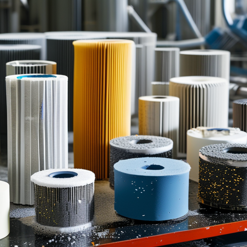
In silicon filtration, the 0.1–1 µm range looks narrow, but it covers different contamination risks. A 1 µm depth medium can capture larger agglomerates while maintaining useful flow. A 0.2 µm membrane provides a tighter barrier for fine particles. However, it may block quickly when the fluid carries unstable clusters. At 0.1 µm, pore definition and test methods matter greatly. Smaller is not always better.
For abrasive slurries, staged depth filtration can protect the final membrane. The first layer catches oversized solids and fragile agglomerates. The final layer addresses the remaining submicron load. In ultrapure water or sensitive chemical service, low extractables, stable wetting, and material compatibility also matter. A filter may meet its pore rating yet release particles or resist flow after installation. I have seen teams focus on retention and overlook pressure decay testing. That omission can become expensive. Not always.
Buyers should map each risk to measurable requirements, including particle distribution, concentration, temperature, viscosity, and allowable pressure drop. Ask whether the rating is nominal or absolute. Request batch records and integrity-test data. Trial the media with the real process fluid, not only clean water. This is where many comparisons become less certain. A practical choice balances retention, service life, cleanliness, and controlled changeouts. Keep it measurable.
Membrane media with 0.1–0.2 µm nominal ratings are typically selected for the highest-risk submicron contamination steps, while 0.45–1.0 µm media are more commonly used for upstream particle control, prefiltration, or lower-criticality fluid streams. Actual retention depends on pore-size test method, differential pressure, fluid chemistry, and filter integrity.
PTFE membranes rated at 0.1 to 0.2 µm are widely considered for aggressive process chemicals. Their fluoropolymer structure offers strong resistance to acids, solvents, and oxidizing fluids. In silicon manufacturing, this matters near wet benches and chemical delivery points. Small particles can damage surfaces, clog narrow channels, or affect yield. Clean filtration is not optional.
The rating alone is not enough. A 0.1 µm membrane may provide tighter particle control, but it can increase pressure drop and reduce flow. A 0.2 µm option may support higher throughput. Process temperature, chemical concentration, pressure, and exposure time must be checked together. I have seen buyers compare pore sizes while overlooking seal compatibility. That mistake can create leaks.
Ask for chemical compatibility data, extractables information, and documented integrity-test methods. Confirm whether the filter is suitable for the actual fluid, not a diluted laboratory sample. Inspect the housing connection as well. A strong membrane cannot compensate for poor installation. Trial testing with real process conditions is valuable, although it takes time and chemical handling discipline. Some specifications still remain uncertain until production data appears. Nakne
Polypropylene depth media is a practical prefiltration choice for silicon processing lines. Its 1–10 µm range helps remove suspended particles before finer filtration stages. High-flow designs can protect pumps, tanks, and downstream membrane filters. In a pilot line, the pressure gauge often reveals more than the catalog rating. A rising differential pressure shows real particle loading.
The selected pore grade should match the process fluid and contamination profile. A 10 µm element may handle heavy upstream debris, while a 1 µm grade offers tighter particle control. Smaller ratings can increase pressure loss. That tradeoff matters during continuous operation. Polypropylene also provides broad chemical compatibility, but temperature, solvent exposure, and cleaning conditions still require verification. Never rely on material names alone.
Housing geometry affects usable capacity. Uneven flow can leave parts of the media clean while other areas become blocked early. Operators should record initial pressure, flow rate, temperature, and replacement pressure. A simple log supports defensible purchasing decisions. One common mistake is selecting only by nominal micron size. That approach can overlook particle shape, concentration, and viscosity. Testing with representative process fluid is better. Results may not be perfect on the first trial. Adjusting the grade after measured data is often more reliable than choosing the tightest filter immediately.
CMP Slurry Filters: 0.5–1.0 µm Media for Defect-Control Tradeoffs
In silicon wafer processing, filter media between 0.5 and 1.0 µm can influence defect performance, flow stability, and equipment uptime. A smaller rating may capture more particles, but it can also increase pressure drop. Small shifts matter. Slurry temperature, solids loading, and viscosity change the real operating result.
During production trials, buyers should compare initial and end-of-life differential pressure. A filter that starts at 0.5 bar may reach an unacceptable level after several hours. The finer medium can also reduce flow if the housing area is undersized. That creates pump stress and uneven delivery across polishing tools. A 1.0 µm medium may provide better throughput, yet it could allow critical agglomerates to pass. The correct choice depends on particle data, not the label alone.
Ask suppliers for retention-test methods, extractables data, particle-shedding results, and chemical compatibility records. Nominal and absolute ratings are not interchangeable. Confirm the test fluid resembles the actual slurry. Water-only testing can hide important behavior. Our early assumption was that finer always meant safer; process data challenged it. A practical evaluation should include wafer defect maps, removal-rate variation, filter life, and pressure trends across multiple lots. Even then, the result may need revision when slurry chemistry changes. A clean test room does not guarantee stable production.
2026 Top Filter Media for Silicon Industry Buyers?
Buyer Metrics: 18.2 MΩ·cm UPW, ISO Class 1, ΔP, and Extractables
In silicon manufacturing, filter media selection starts with evidence, not catalog claims. Buyers should verify stable 18.2 MΩ·cm UPW performance at the actual flow rate. Water resistivity can fall after installation. That detail matters. Qualification tests should record inlet pressure, outlet pressure, temperature, flow, and particle counts. ΔP must remain predictable during the intended service interval.
A low initial ΔP can mislead. Some media load quickly after a clean start. Test for that. ISO Class 1 environments demand disciplined handling, packaging, and installation. Media alone cannot create a cleanroom result. It must support the complete contamination-control process. Operators should inspect seals, connections, and exposed surfaces before production use.
Extractables deserve equal attention. Request data for TOC, ionic species, metals, and residues under realistic UPW exposure. Short soak tests may miss slower release. Use time points that reflect actual wetting and operation. In practical reviews, I compare lot records, test methods, and acceptance limits before approving a sample. Still, no metric is perfect. Flow changes, operator technique, and aging can distort results. Buyers should challenge gaps, repeat critical tests, and document why a compromise was accepted.
| Filter media | Typical nominal / absolute rating | UPW suitability at 18.2 MΩ·cm | Initial ΔP* at 20–25 °C | Extractables buyer screen** | Thermal / chemical profile | ISO Class 1 considerations |
|---|---|---|---|---|---|---|
| PES membrane | 0.04–0.20 µm; absolute retention commonly specified for critical liquid service | Strong choice for final UPW and chemical filtration when pre-rinsed and validated for ionic cleanliness | 0.05–0.25 bar at 10–20 L/min·m², depending on pore size and construction | Target after validated rinse: TOC ≤10 ppb; individual ionic species typically screened at ≤1 ppb | Good aqueous compatibility; moderate temperature capability, commonly used below approximately 80–90 °C | Suitable only with low-shedding construction, controlled packaging, and installation in an ISO 14644-1 Class 1 environment |
| PTFE membrane | 0.02–0.20 µm; hydrophilic grades preferred for aqueous UPW service | Very strong chemical resistance; hydrophobic grades require wetting and are generally better suited to gas or solvent duties | 0.08–0.40 bar at 10–20 L/min·m², with lower resistance often achieved by larger-pore grades | Target after validated rinse: TOC ≤10 ppb; fluoride and other ions must be specifically verified | Excellent resistance to aggressive acids, bases, and solvents; temperature capability can exceed 100 °C depending on support and assembly | Low particle shedding is achievable; verify support materials, seals, packaging, and particle-release test results |
| PVDF membrane | 0.05–0.22 µm; commonly used for fine aqueous and chemical filtration | Good option for many UPW applications after confirming extractables, wetting behavior, and long-term resistivity stability | 0.06–0.30 bar at 10–20 L/min·m² | Target after validated rinse: TOC ≤10 ppb; monitor fluoride, sulfate, and process-specific ions | Good mechanical strength and broad aqueous compatibility; chemical resistance varies by solvent and concentration | Use cleanroom-compatible packaging and verify particle contribution under actual flow and pressure cycling |
| Polypropylene depth media | 1–20 µm nominal; typically used as a prefilter rather than a final UPW barrier | Useful upstream for particulate loading control; generally not selected alone for final 18.2 MΩ·cm UPW filtration | 0.02–0.15 bar at 5–15 L/min·m², depending on grade and solids loading | Target after validated rinse: TOC ≤20 ppb for prefiltration; ionic profile must be checked for the process | Good resistance to many aqueous chemicals; temperature commonly limited to approximately 80–90 °C | Select low-shedding fibers and sealed edges; avoid exposed media in the final critical zone unless validated |
| Borosilicate glass-fiber depth media | 0.7–3.0 µm nominal; high dirt-holding capacity for upstream clarification | Appropriate for upstream particle reduction only; not normally the final barrier for high-purity UPW | 0.03–0.20 bar at 5–15 L/min·m², increasing with solids loading | Require low-binder or binder-free construction; screen TOC, boron, silica, and particle release | High surface area and good thermal stability; chemical compatibility depends strongly on pH and binder chemistry | Not preferred in the final ISO Class 1 critical path unless particle shedding and fiber migration are specifically controlled |
| Regenerated cellulose membrane | 0.10–0.45 µm; selected for specific aqueous analytical or process duties | Can be used in compatible aqueous streams, but is less broadly preferred for aggressive semiconductor chemicals | 0.05–0.30 bar at 10–20 L/min·m² | Target after validated rinse: TOC ≤10 ppb; screen cellulose-related organics and bioburden where relevant | Good wettability; limited resistance to strong acids, strong bases, and many organic solvents | Use only after cleanroom particle, extractables, and chemical-compatibility qualification |
* ΔP basis: Values are indicative clean-filter ranges and are not directly comparable without controlling effective filtration area, flow rate, viscosity, temperature, pore-size method, and test fluid. The buyer should specify a maximum clean ΔP and an end-of-life ΔP.
** Extractables basis: TOC and ionic values are procurement screening targets, not universal material guarantees. Validate using the actual rinse protocol, contact time, temperature, chemical composition, and analytical detection limits.
UPW note: 18.2 MΩ·cm at 25 °C describes the resistivity of the water system, not the nominal performance of the filter media. A filter should be qualified to avoid measurable contribution to resistivity loss, TOC, ions, particles, and microbial burden.
sale@harbertpump.com,
sale@harbertpump.com